- sales@motionsensors.com
- Monday - Thursday: 8AM to 5PM EST
- 252-331-2080

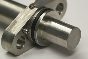
HD Series Practical Application Guide
Motion Sensors offers a full range of standard speed solutions. Our standard speed sensors — and application experts who understand your requirements — make Motion Sensors your go-to source for standard speed sensing solutions.
Duty Cycle
The duty cycle and its relationship to the phase shift between output A and output B to a large part determines the output signal performance of the sensor. In the ideal sensor, the duty cycle of the output is always 50%. In the real world, the duty cycle is rarely ever 50% even if you could create a perfect target gear. Mismatch in the duty cycles between outputs A and B will result in a phase shift error of 3.6° for every 1% of duty cycle mismatch. This error occurs when the direction of the target gear changes and the trailing edges of the output become the leading edges.
If the duty cycle mismatch between outputs A and B is 5%, the phase shift error will be 18°. The sensor can be rotated to distribute the error evenly but the phase shift error will be 9° in each direction.
If the duty cycle of output A is greater than the duty cycle of output B, the counterclockwise duty cycle will be greater than 90° and the clockwise duty cycle will be less than 90°.
If the duty cycle of output A is less than the duty cycle of output B, the counterclockwise duty cycle will be less than 90° and the clockwise duty cycle will be greater than 90°.
So, how is the duty cycle relevant to your application?
Asymmetry of the target gear due to manufacturing tolerances will directly affect the output duty cycles. This asymmetry will add to the inherent duty cycle errors of the sensor. In some cases this can actually make the duty better and in some cases can make the duty cycle worse. Sensing the face of a gear is a common applicator for speed sensors. It is not uncommon for face cut gears to be highly asymmetrical. Due to physical limitations, the hall-effect elements in the sensor cannot be oriented on the same radius on the face of the target gear. This means that the change in duty cycle for each output may vary slightly increasing the phase shift error compared to sensing the perimeter of a target gear.
Air Gap
The air gap between the target gear and the face of the sensor also plays a role in the duty cycle performance. The magnitude of the duty cycle error is directly proportional to the air gap between the sensor face and the target gear. A sensor with a duty cycle error of 2% at an air gap 0.025” will increase at an air gap of 0.75”. This increase will primarily depend on the uniformity of the magnetic field strength of the sensor. Larger air gaps will always result in a performance degradation of the output compared to smaller air gaps.
Alignment
Alignment of the sensor to the face of the target gear will significantly impact the phase shift performance of the sensor. For sensors that cannot be rotated due to mounting flanges, custom aligned sensors may be required to satisfy the application requirements. All standard HD series sensors are aligned with a 12 pitch gear. If the user application requires sensing of a different pitch gear, for example a 20 pitch gear, there will be a significant error in the phase shift setting. To get an idea of how sensitive the alignment is as a function of target gear pitch, when sensing a 20 pitch gear a 1° rotation in the alignment of the sensor will result in a 6.1° change in the duty cycle.
Magnetic Fields
One of the often overlooked error sources is stray magnetic fields. Electronic devices such as motors and solenoids can create large transient magnetic fields. If these fields are strong enough, they can significantly influence the performance of the sensor. If they are close in strength to the sensor bias magnet, they can actually cause a false pulse transition on the output. Always locate the sensor as far away from potential stray magnetic fields as possible.
Understanding how the sensor will work in your application is critical to ensuring the maximum performance of the sensor. Motions Sensors is here to help you meet your application performance requirements. Contact our Engineering Department at eng@motionsensors.com or call us today at 252-331-2080 to discuss your application requirements.
Related Links: