- info@motionsensors.com
- Monday - Thursday: 8AM to 5PM EST
- 252-331-2080
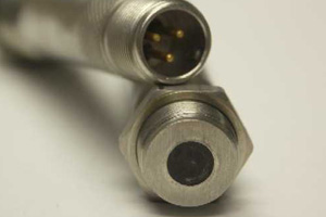
Amplified (Active) Speed Sensors
Digi-Pulse speed sensors combine high-sensitivity amplifiers with variable reluctance (VR) or modulated carrier transducers (RF). Unique features include near zero velocity (2 Hz) speed sensing, large air gap capability, and several choices of digital output. By combining the sensor and preamplifier in one unit, reductions in overall cost can be attained especially when preamplifier enclosures and installation labor are considered.
Digi-Pulse sensors are available in both hermetically sealed and encapsulated models and can be customized to satisfy specific requirements. These sensors also have EU certification for emissions and immunity (CE mark) and comply with EMC directive 89/336/EEC for installation into any environment.
CUSTOM MODELS
In addition to our standard models, active amplified speed sensors are available in custom lengths, diameters, configurations, and mounting threads. Custom operating specifications (output options, etc.) are available, as well as options such as pigtail leads or NPT threading. See additional sensor customization options.
Active Speed Sensors
Active, or amplified sensors with digital output offer a low-cost solution for interfacing directly to data acquisition systems. These sensors integrate a preamplifier/signal conditioner within the sensor housing and offer the advantages of excellent noise immunity and greater transmission capability.
Input power supply requirements cover the most popular ranges for both commercial and industrial use. The output frequency of these sensors has a square pulse waveform (digital) that directly relates to the number of turbine blades, gear teeth, etc. that have been sensed. These pulses, in turn, can be correlated to determine flow rate, RPM, or velocity.
- Features & Specifications
- Standard Models
Type
Magnetic (inductive or variable reluctance) or RF (modulated carrier)
Warranty
Unconditional one (1) year warranty if used within specifications.
Physical Features
- Body material: 300 series stainless steel
- Encapsulation: epoxy potting or hermetically sealed, welded construction
- High Shock and Vibration resistance - MIL-STD-202G METHOD 214A, Test Condition H
Input Power
8 to 30 VDC, 10 mA max. @ no load Reverse polarity protected
Pulse Output Options
- Open collector; maximum OFF current 30 VDC, maximum ON current 400mA
- TTL/CMOS: fan-out of 5 TTL/CMOS loads
- 0-10 VDC square wave (requires 15-30 VDC input power)
Interconnection Options
- Three (3) pin MIL-C-5015 type connector with gold plated pins; mates with MS3106-10SL-3S; other connector types upon request.
- Pigtail with wires or cables.
- NPT threaded body with wire or cable pigtail for explosion proof environments.
Operating temperature: -40°C to +85°C
Storage temperature: -65˚C to +125°C
NOTE: units that operate up to 125°C are also available
Pin/Pigtail Connections
- Pin A (Red): Input Power (+)
- Pin B (Black): Common (-)
- Pin C (White): Pulse Output (+)
Airgap
Up to 0.140" dependent on target geometry and sensor construction.
Approvals
CE compliant to EMC Directive 2004/108/EC for use in residential, commercial, light industrial and heavy industrial environments.
![]() |
MODEL NUMBER | MOUNTING THREAD (A) | THREAD LENGTH (B) | OVERALL LENGTH (C) | TIP (Length/Dia.) (D) | OUTPUT (Pulse Range) |
DR-014 | 5/8x18 | .875 | 3.6 | Flush Front | Open Collector |
DR-002 | 5/8x18 | .875 | 3.6 | Flush Front | 0-5 VDC |
DR-013 | 5/8x18 | .875 | 3.6 | Flush Front | 0-10 VDC |
DR-007 | 11/16x24 | .875 | 3.6 | Flush Front | Open Collector |
DR-001 | 11/16x24 | .875 | 3.6 | Flush Front | 0-5 VDC |
DR-003 | 11/16x24 | .875 | 3.6 | Flush Front | 0-10 VDC |
NOTES:
Dimensions in inches
Specifications +/-10%
Mounting threads UNF-2A
Active Speed Sensors - Variable Reluctance
Active, or amplified sensors with digital output offer a low-cost solution for interfacing directly to data acquisition systems. These sensors integrate a preamplifier/signal conditioner within the sensor housing and offer the advantages of excellent noise immunity and greater transmission capability.
Input power supply requirements cover the most popular ranges for both commercial and industrial use. The output frequency of these sensors has a square pulse waveform (digital) that directly relates to the number of turbine blades, gear teeth, etc. that have been sensed. These pulses, in turn, can be correlated to determine flow rate, RPM, or velocity.
- Features & Specifications
- Standard Models
Type
Magnetic (inductive or variable reluctance) or RF (modulated carrier)
Warranty
Unconditional one (1) year warranty if used within specifications.
Physical Features
- Body material: 300 series stainless steel
- Encapsulation: epoxy potting or hermetically sealed, welded construction
- High Shock and Vibration resistance - MIL-STD-202G METHOD 214A, Test Condition H
Input Power
8 to 30 VDC, 10 mA max. @ no load Reverse polarity protected
Pulse Output Options
- Open collector; maximum OFF current 30 VDC, maximum ON current 400mA
- TTL/CMOS: fan-out of 5 TTL/CMOS loads
0-10 VDC square wave (requires 15-30 VDC input power)
Interconnection Options
- Three (3) pin MIL-C-5015 type connector with gold plated pins; mates with MS3106-10SL-3S; other connector types upon request.
- Pigtail with wires or cables.
- NPT threaded body with wire or cable pigtail for explosion proof environments.
Temperature Range
- Operating: -40˚C to +85˚C
- Storage: -65˚C to +125˚C
NOTE: units that operate up to +125˚C are also available
Pin/Pigtail Connections
- Pin A (Red): Input Power (+)
- Pin B (Black): Common (-)
- Pin C (White): Pulse Output (+)
Airgap
Up to 0.140" dependent on target geometry and sensor construction.
Approvals
CE compliant to EMC Directive 2004/108/EC for use in residential, commercial, light industrial and heavy industrial environments.
![]() |
MODEL NUMBER | MOUNTING THREAD (A) | THREAD LENGTH (B) | OVERALL LENGTH (C) | TIP (Length/Dia.) (D) | OUTPUT (Pulse Range) |
DM-010 | 5/8x18 | .875 | 3.5 | .031/.100 | Open Collector |
DM-002 | 5/8x18 | .875 | 3.5 | .031/.100 | 0-5 VDC |
DM-011 | 5/8x18 | .875 | 3.5 | .031/.100 | 0-10 VDC |
DM-13 | 11/16X24 | .875 | 3.6 | .075/.105 | Open Collector |
DM-001 | 11/16X24 | .875 | 3.6 | .075/.105 | 0-5 VDC |
DM-002 | 11/16X24 | .875 | 3.6 | .075/.105 | 0-10 VDC |
NOTES:
Dimensions in inches
Specifications +/-10%
Mounting threads UNF-2A
Active VR Speed Sensors - EMI Susceptibility Hardened
DME Series
Motion Sensors DME series of active variable reluctance (VR) speed sensors are similar to our standard DM series amplified sensors. The DME series offers EMI (Electromagnetic Interference) susceptibility hardening and improved performance in environments with greater external electrical noise and disruptions. The DME series is equivalent to the Honeywell 584xx series while also offering CE compliance and additional pulse output offerings.
Specification Comparison with Motion Sensors DM Series
DME Series DM Series
Input Power 5 - 30 VDC 8 - 30 VDC
Reverse Polarity Yes Yes
Short Circuit Protection No Yes
Current Draw 21mA @ 30VDC 30mA @ 30VDC
Frequency Response 10Hz - 10KHz 0Hz - 10KHz
Air Gap Capability .118"* .140"*
CE Compliance Yes Yes
*Units that operate up to +125˚C are also available
- Features & Specifications
- Standard Models
Type
Variable Reluctance (Magnetic) with EMI susceptibility hardening
Physical Features
- Body material: 300 series stainless steel
- Encapsulation: epoxy potting
- High Shock and Vibration resistance: MIL-STD-202G METHOD 214A, Test Condition H
Input Power
- 5 to 30 VDC, 25 mA max. @ 30VDC
- Reverse polarity protected
Pulse Output Options
Guaranteed power on state at Logic 0
- Supply Tracking
Guaranteed power on state at Logic 0
Logic 0:
0.35 VDC Max @ 15VDC
0.80 VDC Max @ 30 VDC
Logic 1:
(VS x RL)/(RL+2200)
Open Collector
Logic 0:
0.35 VDC Max @ 15VDC
0.80 VDC Max @ 30 VDC
Logic 1:
(VS x RL)/(RL+Y*)
*Y=value of external pullup resistor
- TTL/CMOS: fan-out of 5 TTL/CMOS loads
Logic 0:
0.35 VDC Max @ 15VDC
0.80 VDC Max @ 30 VDC
Logic 1:
5 VDC +/- 0.5 VDC
0-10 VDC square wave (requires 10-30 VDC input power)
Logic 0:
0.35 VDC Max @ 15VDC
0.80 VDC Max @ 30 VDC
Logic 1:
10 VDC +/- 1.0 VDC
Interconnection Options
- Three (3) pin MIL-C-5015 type connector with gold plated pins; mates with MS3106-10SL-3S
- M12x1 threaded 5 pin connector
- Other connector types upon request
- Pigtail with wires or cables.
NPT threaded body with wire or cable pigtail
Temperature Range
- Operating: -40˚C to +125˚C
- Storage: -65˚C to +125˚C
Pin/Pigtail Connections
- Pin A (Red): Input Power (+)
- Pin B (Black): Common (-)
- Pin C (White): Pulse Output (+)
Airgap
Up to 0.140" dependent on target geometry and sensor construction.
Approvals
CE compliant to EMC Directive 2004/108/EC for use in residential, commercial, light industrial and heavy industrial environments.
VR Standard Active Speed Sensors |
MODEL NUMBER | MOUNTING THREAD (A) | THREAD LENGTH (B) | OVERALL LENGTH (C) | TIP (Lenth/Dia.) (D) | OUTPUT (Pulse Range) |
DME-1 | 15/8x18 | .875 | 3.5 | Flush Front | Open Collector |
DME-2 | 15/8x18 | .875 | 3.5 | Flush Front | 0-5 VDC |
DME-3 | 15/8x18 | .875 | 3.5 | Flush Front | 0-10 VDC |
NOTES:
Dimensions in inches
Specifications +/-10%
Mounting threads UNF-2A