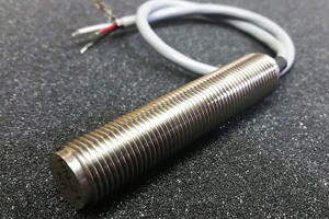
The H series of sensors is based on Hall Effect sensor technology, which can sense a change in target motion from true zero to 20 KHz. These sensors incorporate a magnet within the sensor, enabling them to sense ferrous metal as well as magnet targets and can be optimized to detect fine as well as large pitch targets. These sensors integrate a preamplifier/signal conditioner within the sensor housing that provides excellent noise immunity and greater transmission capability. The output frequency of these sensors has a square pulse waveform (digital) that directly relates to the number of turbine blades, gear teeth, etc. that have been sensed. These pulses, in turn, can be correlated to determine flow rate, RPM, or velocity.
In addition to the standard models, oriented hall effect sensors are available in custom lengths, diameters, configurations, and mounting threads. Motion Sensors also offers Intrinsically Safe versions for applications or environments that require Intrinsic Safety, as well as Explosion Proof versions for potentially explosive atmospheres.
- Features & Specifications
- Standard Models
- 4.7 to 24 VDC regulated, 15 mA maximum @ no load
- Reverse polarity protected
Pulse Output Options
- TTL/CMOS (Standard): fan-out of 5 TTL/CMOS loads
- Open collector
- Supply tracking: logic 0: 0.4 VDC
- logic 1: (VS-0.2)xRL/(RL+2200)
Up to 0.100″ dependent on target geometry and sensor construction
- Magnet that resists demagnetization
- Focusing tip
- Three (3) pin MIL-C-5015 type connector with gold plated pins; mates with MS3106-10SL-3S; other connector types upon request
- Pigtail with wires or cable
- NPT threaded body with wire or cable pigtail for explosion proof environments
Unconditional one (1) year warranty if used within specifications
- Pin A (Red): Input Power (+)
- Pin B (White): Pulse Output (+)
- Pin C (Black): Common (-)
- Operating temperature:
-40°C to +125°C with connector
-40°C to +105°C with pigtail
NOTE: units that operate up to 150°C
are also available
- Storage temperature:
-40°C to +150°C with connector
-40°C to +105°C with pigtail - Body material: 300 series stainless steel
- Encapsulation: epoxy potting or hermetically sealed, welded construction
- High Shock and Vibration resistance (MIL-STD-202G METHOD 214A, Test Condition H)
Alignment of the sensor to target rotation is required for optimal performance, ensuring proper orientation of the hall effect element to the magnetic field
CE compliant to EMC Directive 2004/108/EC for use in residential, commercial, light industrial and heavy industrial environments
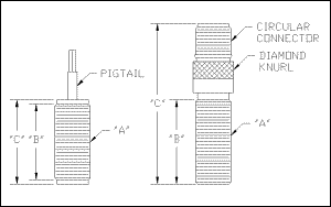
| MODEL NUMBER | MOUNTING THREAD (A) | THREAD LENGTH (B) | OVERALL LENGTH (C) | CONNECTION TYPE | OUTPUT (Pulse Range) |
| H-1 | 5/8X18 | 1.43 | 2.86 | Connector | Open Collector |
| H-2 | 5/8X18 | 1.43 | 2.86 | Connector | 0-5 Vdc |
| H-3 | 5/8X18 | .85 | 1.00 | Pigtail | Open Collector |
| H-4 | 5/8X18 | .85 | 1.00 | Pigtail | 0-5 Vdc |
| H-5 | 5/8X18 | 1.35 | 1.50 | Pigtail | Open Collector |
| H-6 | 5/8X18 | 1.35 | 1.50 | Pigtail | 0-5 Vdc |
| H-9 | 5/8X18 | 1.43 | 2.86 | Connector | 0-10 Vdc |
| H-10 | 5/8X18 | 1.43 | 2.86 | Connector | Supply Tracking |
| H-11 | 5/8X18 | .85 | 1.00 | Pigtail | 0-10 Vdc |
| H-12 | 5/8X18 | .85 | 1.00 | Pigtail | Supply Tracking |
| H-13 | 5/8X18 | 1.35 | 1.50 | Pigtail | 0-10 Vdc |
| H-14 | 5/8X18 | 1.35 | 1.50 | Pigtail | Supply Tracking |
NOTES:
Dimensions in inches
Specifications +/-10%
Mounting threads UNF-2A